Spaces between posts

I have been searching and searching and found so many instructions on how to remove the spacing between the posts.

I tried editing the HTML changing different themes and nothing worked. And found this silly thing while browsing through all the options on the dashboard.

"Show ads on blog" and this was chosen to be a "YES". Changed this to "NO" and Alas !! there you go.. the spacings between the posts became normal.

Go to the blog Dashboard >> click Earnings

On the right hand side, "Show ads on blog" Choose "NO"

I hope someone will find this information usefull.

ARP and ICMP protocols explained


ARP: Address Resolution Protocol


In order for the ip communication to take place between 2 computers it is necessary that the MAC address should be known to each other. If device A with ip address "192.168.1.11" needs to communicate with device B with IP address "192.168.1.1" and transfer data, device A should know the MAC address of device B.

* Used to find unknown MAC address using a known IP address.
* Used to find IP conflicts in the network.
* It is generated in the network layer and covered by datalink layer.


ICMP: Internet Control Message Protocol

* ICMP is a protocol generated in the Network Layer.
* This is the protocol used when you a ping(Packet Internet Groper) an IP address.
* While we ping an ip address, it will check the routing table.
* It will send echo requests and reply and shows success message if it is reachable or an error messages if it is not reachable.

While pinging if you get a "Destination Host Unreachable" message it means that the routing table does not have the network for the ip address you pinged. In this case the ping packet will not go out of your network as there is no route to reach the destination.

If you get "Request Timed Out" it means that it does have a rout to reach the pinged ip address but it will not get a reply from the pinged ip address.


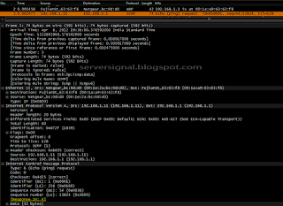
Below is an illustration to explain ARP.


Now that the source knows the destination MAC they both can communicate with each other. As part of the PING request, the source generates an ICMP packet and then the destination responds back making the PING successfull.
PING request (ICMP prototol)

PING response(ICMP protocol)

And you get


IP ADDRESS (Internet Protocol Address) & Subnet Mask

There are 2 versions of IP addresses. IP version 4 and Version 6.

Ip version 6 will be soon introduced in real times. I will discuss ip version 6 on a later chapter. As of now lets discuss the ip version 4 which is the addressing scheme in use now.

Ip stands for Internet protocol. Formed by IANA(Internet Assigned Numbers Authority and ICANN(Internet Corporation for Assigned Number and Names).

* IPV4 is a logical address of 32 bits.
* An ip address is a combination of Network id and Host id just like a telephone number is a combination of area code and telephone number.
* First part is always the network part.

Each bit denotes a value of either 1 or 0. The 32 bit address is divided equally into 4 bytes.


IPv4 has 2 types.

1. Private which is used within a LAN. eg: at home
2. Public used in WAN. eg: Internet

PRIVATE IP address has 3 classes

Class A : 10.0.0.0 - 10.0.0.255

Class B : 172.16.0.0 - 172.31.255.255

Class C : 192.168.0.0 - 192.168.255.255

Apart from the above discussed ranges rest of the ip addresses are all public ip addresses.

PUBLIC IP address has 5 classes

Class A : 1.0.0.0 - 126.255.255.255 (1-126 network)
(127 network is reserved for loop back)

Class B : 128.0.0.0 - 191.255.255.255 (128-191 network)

Class C : 192.0.0.0 - 223.255.255.255 (192-239 network)

Class D : 224.0.0.0 - 239.255.255.255 (224-239 network)

Class E : 240.0.0.0 - 255.255.255.255 (240-255 network)


SUBNET MASK

When you assign an ip address to a system, the system identifies the network part and host part of the ip address by looking at the subnet mask address.

All 1s on the network part and all 0s on the host part makes a subnet mask.

Look at the table.


DEFAULT GATEWAY

A default gateway can be termed as an access point to another network.

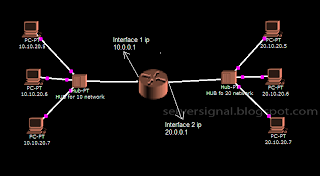
Suppose a computer in the 10 network needs to communicate with a computer in 20 network. Here comes the use a router. A router is used to connect 2 different networks. In the below picture you can see 2 networks. A connection is possible between these 2 networks using a router in between.


The interface where the 10 network is connected has an ip address 10.0.0.1 and the interface where 20 network is connected has an ip address 20.0.0.1.

10.0.0.1 is the gateway for computers in 10 network and
20.0.0.1 is the gateway for computers in the 20 network.


BROADCAST IP ADDRESS

As the term means, a broadcast ip address is used to sent a broadcast packet. In other words, if a packet or data needs to be sent to all computers in a specified network, broadcastip address is used.

By now you must be able to identify the network part and host part of an ip address. For an ip address 10.0.0.1, the first octet is the network part and the last 3 octets is the host part. Hence this ip belongs to the network 10.0.0.0. The broadcast ip for 10 network would be 10.255.255.255.

Similarly for an ip address 192.16.20.3, the network part is the first 3 octets and last octet is the host. Hence this ip belongs to the network 192.16.20.0. The broadcast ip for the network 192.16.20.0 is 192.16.20.255.

When you get all 1s on the host part and not changing anything on the network part you get the broadcast ip.

OSI Layers


OSI (Open System Interface)

It defines how data communication happens, the protocols involved.


PHYSICAL LAYER

* First layer of OSI model.
* Represents the bits.
* It deals with :-
Transmission media for data communication.
Electrical and mechanical functions of interface or ports or media.
Procedures and functions of transmission media.

Examples:
Hardware: Network adapter, Repeater, Network hub, Modem, Fiber Media Converter.
Protocols: DSL, ISDN all the physical topologies etc..


DATA LINK LAYER

* Second Layer
* Converts bits(0s and 1s) into Frames.
* Data link layer moves the frames from one hop to the other(from one network to the other).
* Physical addressing.
* Flow control.
* Error detection and error notification.
To detect errors, it uses a technology called CRC(Cyclic Redundancy Check).
* FCS (Frame Check Sequence)
* Access control >> The sender takes control of the reciever. Sender decides when to send the data.
* LLC and MAC work at this layer.

MAC Layer : It does the framing, physical addressing, line discipline, Error notification and error detection.

LLC Layer : Sequencing of bits and identifying the upper layer protocol.

Protocols : ARP, ARCnet, ATM, IEEE 802.2 (provides LLC functions to IEEE 802 MAC layers), IEEE 802.11 wireless LAN, Network Discovery, PPP, Frame Relay, Token Ring.


NETWORK LAYER

* Frames are converted to packets.
* Encapsulation of IP address takes place.
* Logical addressing.
Note: Addressing is done at the data link layer as well, but those addresses refer to local physical devices. In contrast, logical addresses are independent of particular hardware

and must be unique across an entire internetwork.
* Routing :- Determines the route through which the data has to be travelled.

Protocols: ipv4, v6, ICMP, IPsec, RIP, DDP.


TRANSPORT LAYER


* Packets are converted into segments.
* Sequencing : For each segment a sequence number is given. Each segment is put into correct sequence.
* Port addressing. Port service is chosen by Transport layer.
* Flow control: To avoid overloading, it controls the flow of data between 2 devices.
* Controls the flow of data.
* Error Control: Data is re-send from the source in case of error detection.

Protocols: TCP, UDP


SESSION LAYER

* Session is referred to as a network dialog. This is the layer which controls the network dialog between source and destination.
* Services like http, https, ftp etc are identified in this layer.
* It establishes, manages and terminates a session. This 3 step process is called dialog control.
* It creates synchronisation points/checkpoints which helps in continous flow of data in case a session is cut during communication.
* Mode of communication. ie 1.Duplex 2.Full Duplex 3. Semi-duplex.

Untill now the data is in the form of bits (os and 1s)


PRESENTATION LAYER

* Acts as a translator.
* Identifies the format of data.
* Encryption and Decryption is done in the layer.
* Compression and decompression.


APPLICATION LAYER

* It is the interface between user and application.
* E-mail comes in the application layer.
* File management, File transfer, file access, AD services are all in apllication layer.


Process of Encapsulation

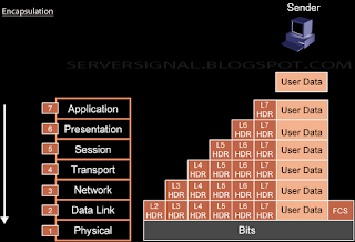
If a data has to be transmitted it must be packaged by a process called encapsulation. As data moves down through each layer, each layer adds it's own header to the data before passing it to the next layer.

Below diagram will give you a better understanding.

Windows reboot loop "Configuring Updates: Stage 3 of 3"

This applies to Windows Vista, Windows 7 and Windows 2008 servers.

This usually happens after a windows update as was for me but also occurs when you update some drivers. Some commands which requires a reboot.

Your OS might scare you when you reboot and it says:  "Configuring Updates: Stage 3 of 3"

Dont worry try the following :-

1. Get into advanced boot options by hitting on F8 key. Try "Last Known Good Configuration". I promise this will not resolve your issue, but still it's worth giving a try.

2. Now that doesn't work. Get the respective OS installation CD and insert it into the CD drive. Reboot the computer and again get into advanced boot options, and select "Repair your computer" choose "Command Prompt" in the recovery choices.

3. Enter the following command:-

del C:\Windows\winsxs\pending.xml

4. Exit and reboot.

Good luck !!!!