Resolve RUNDLL error

The below error may come up when you boot up the computer or when you open an application.


Here is how you will solve this.

Go to Start >> Run >> Type Regedit and hit enter.

This will open the windows registry.

Expand: HKEY_CURRENT_USER >> Software >> Microsoft >> Windows >> Current Version >> highlight Run >> Delete the value which includes "rundll" and delete it.

Reboot the machine.

If you do not find this under HKEY_CURRENT_USER try the same location under HKEY_LOCAL_MACHINE.

Let me know if this was helpfull :-)

Kill a process which is hung

Many a time while troubleshooting issues with various applications I have had troubles with services going to a hung state. When the service is in a stopping state you can simply go ahead and kill it from the task manager but what when it is hung at "starting" ? Also not all services run as processes in task manager. For instance, if Exchange POP3 service is stuck in a 'stopping' state. You cant go into task manager and kill the process because its not there. And there isnt a way to force a service to stop in the service manager.

The following commands had been a great help for me.

To kill any process be it hung at "stopping" or "starting" state do the following :-

Open command prompt in elevated mode ie; right click on command prompt and "Run as Administrator".

Enter the following command:
sc queryex (service name)
This will give you the PID(process id) To get the service name, right click on the service under general tab you can see Service Name listed.

Then enter the following command:
taskkill /f /pid (Process id)

Hope you found it usefull.

Note: The process id will keep changing, hence always check the process id before running the taskkill command.

SAN zoning


In any network when a switch is initiated, a connection is established between all devices connected to it. So is in a SAN network. A "Fabric" in a SAN environment is referred to a SAN switch. A network without any restrictions to the storage unit compromises on security, availability and management of storage. This problem can be solved by "Zoning" which is a feauture in fabric switches. Zoning creates rules restrictions as in what FC device can see what other devices connected on the fabric. This is similar to a V-LAN.

Below figure illustrates Zoning on a Fabric.


Types of Zoning


  • Hardware zoning.
  • Software Zoning.


Hardware Zoning

Fabric port number is used to configure hardware zoning. The physical ports of the fabric are the members. Hardware zoning provides the highest security.

Dissadvantage: Zoning has to be re-configured if the device is connected to a different port.


Software zoning

An HBA card has WWNN(World wide node name) and WWPN(World wide port name). Just like a MAC address goes to ethernet card, WWN goes to HBA card. You don't have to worry about the port on the fabric were the device is connected if it is a software zoning.

For an initiator(servers) WWNN starts with 20:_, WWPN starts with 10:_.
For targets WWNN starts with 50:_.


WWN spoofing

A device can change it's WWN rather using the one given by it's manufacturer. An unknown device can gain trust of a storage device and can access it by spoofing the WWN number.

Commands to mount and open files in a cdrom on Linux

Many of the administrators who are new to linux have problem with opening file from a cdrom or to install application from a CD on a linux platform. The below steps must help you.

# mount /dev/cdrom /cdrom

This will show following result:
mount: mount point /cdrom does not exist.

Now change the directory to / if you are not there:
# cd /

Here create a directory to mount the CD using the following command:
# mkdir cdrom

To mount the D to the "cdrom" directory use the following command:
# mount /dev/cdrom /cdrom

Now change directory to /cdrom:
# cd /cdrom

browse the CD with the "ls" command.

To unmount the CD, change directory back to / followed by the unmount command.

# cd /

# umount cdrom.

Hope that helps...

Cloud Computing Models


While cloud computing is still a relatively new technology, there are generally three cloud service models, each with a unique focus. The American National Institute of Standards and Technology (NIST) defined the following cloud service models:


Software as a service (SaaS)

This capability that is provided to the consumer is to use the applications that a provider runs on a cloud infrastructure. The applications are accessible from various client devices through a thin client interface, such as a web browser (for example, web-based email). The consumer does not manage or control the underlying cloud infrastructure, including the network, servers, operating systems, storage, or even individual application capabilities. One possible exception is for the consumer to continue the control of limited user-specific application configuration settings.

Platform as a service (PaaS)

This capability that is provided to the consumer is to deploy consumer-created or acquired applications onto the cloud infrastructure. Examples of these types of applications include those that are created by using programming languages and tools that are supported by the provider. The consumer does not manage
or control the underlying cloud infrastructure, including the network, servers, operating systems, or storage. But, the consumer has control over the deployed applications and possibly application-hosting environment configurations.

Infrastructure as a service (IaaS)

This capability that is provided to the consumer is to provision processing, storage, networks, and other fundamental computing resources where the consumer is able to deploy and run arbitrary software. These resources can include operating systems and applications. The consumer does not manage or control the underlying cloud infrastructure, but has control over operating systems, storage, and deployed applications. The consumer might also have limited control of select networking components (for example, hosts).

Below figure shows these cloud models:


Cloud Computing Deploying Models:


Private cloud

The cloud infrastructure is owned or leased by a single organization and is operated solely for that organization.

Community cloud

The cloud infrastructure is shared by several organizations and supports a specific community that shares (for example, mission, security requirements,policy, and compliance considerations).

Public cloud

The cloud infrastructure is owned by an organization that sells cloud services to the general public or to a large industry group.

Hybrid cloud

The cloud infrastructure is a composition of two or more clouds (internal, community, or public) that remain unique entities. However, these entities are bound together by standardized or proprietary technology that enables data and application portability (for example, cloud bursting).

Below figure shows cloud computing deploying models:

What is Cloud ?


Cloud computing is a model for enabling universal, convenient, on-demand network access to a shared pool of configurable computing resources (for example: networks, servers, storage, applications, and services). These resources can be rapidly provisioned and released with minimal management effort or service provider interaction. Below figure shows an overview of cloud computing.


Cloud computing provides computation, software, data access, and storage services that do not require user knowledge of the physical location and configuration of the system that delivers the services.


Private and public cloud

A cloud can be private or public. A public cloud sells services to anyone on the Internet. A private cloud is a proprietary network or a data center that supplies hosted services to a limited number of people. When a service provider uses public cloud resources to create their private cloud, the result is called a virtual private cloud. Whether private or public, the goal of cloud computing is to provide easy, scalable access to computing resources and IT services.


Cloud computing components

We describe the cloud computing components, or layers, in our model.

A cloud has four basic components

1. Cloud Services
2. Cloud Infrastructure
3. Cloud Platform
4. SAN + Storage


Cloud Services

This layer is the service that is delivered to the client, it can be an application, a desktop, a server, or disk storage space. The client does not need to know where or how their service is running, they just use it.


Cloud Infrastructure

This layer can be difficult to visualize depending on the final delivered service. If the final service is a chat application, the cloud infrastructure is the servers on which the chat application is running. In the other case, if the final service is a virtualized server, the cloud infrastructure is all the other servers that are required to provide “a server” as a service to the client. Examples of these types of servers include: domain name server (DNS), security services, and management.


Cloud Platform

This layer consists of the selected platform to build the cloud. There are many vendors like IBM Smart Business Storage Cloud, VMware vSphere, Microsoft Hyper V, and Citrix Xen Server, which are well known cloud solutions in the market.


SAN + Storage

This layer is where information flows and lives. Without it, nothing can happen. Depending on the cloud design, the storage can be any of the previously presented solutions. Examples include: Direct-attached storage (DAS), network-attached storage (NAS), Internet Small Computer System Interface (iSCSI), storage area network (SAN), or Fibre Channel over Ethernet (FCoE). For the purpose of this book, we describe Fibre Channel or FCoE for networking and compatible storage devices.

Netbackup Architecture


NetBackup is available in three editions to support organizations ranging from SMBs to large enterprises.
See the table below:

There are two primary architectures deployed by NetBackup
1. Two-Tier (NetBackup Enterprise Server)
2. Three-Tier (NetBackup Server)


To make things easy to understand I will explain Three Tier Architecture first.

NetBackup Enterprise Server Architecture (Three-Tier) 

A typical NetBackup Enterprise Server storage domain consists of one NetBackup Master Server, one or more NetBackup Media Servers, and multiple NetBackup Clients. Large customers often have multiple NetBackup Storage domains spread across data centers.


NetBackup Master Server 
  • Main Backup Server - Manage all operations (Policies, Schedules, Device Configuration, & Catalog)
  • Backs Up and Restores Local and Client Data to Attached Storage (Tape / Disk)
  • Manages Attached (Direct / SAN) Storage 

The NetBackup Master Server is the “brains” for all data protection activities, from scheduling and tracking client backups to managing tape media and more. In addition, the NetBackup Master Server may have one or more storage devices attached for backing up its local data or NetBackup client data across the network. 

NetBackup Media Servers 
  • Backs Up and Restores Local and Client Data to Attached Storage (Tape/Disk)
  • Manages Attached (Direct / SAN) Storage 

Organizations with data in several locations, or with data-intensive applications, may distribute the workload across servers by deploying a NetBackup Enterprise Server as a Media Server. The Master Server is the brains, and the Media Servers are the workhorses of deployments. A NetBackup Media Server can share tape resources with NetBackup Master/Media Servers over a storage area network (SAN) or provide for backup and recovery from its own dedicated storage hardware. If a NetBackup Media Server fails, the attached NetBackup Client backups will be routed to another NetBackup Media Server. 

NetBackup Clients 
  • Prepares and Sends Local Data to NetBackup Master / Media Servers for Storage
  • Receives Stored Data from NetBackup Master / Media Servers for Restoration 

Each system to be protected requires a NetBackup client. The NetBackup client sends and receives data across the local area network (LAN) or storage area network (SAN) to a NetBackup Media Server. 

Each NetBackup Enterprise Server or NetBackup Server license includes the necessary licenses to backup NetBackup data (not other application data). 


NetBackup Server Architecture (Two-Tier) 

Two-tier NetBackup architecture is defined as a single NetBackup server that acts as both a Master and Media Server (Master/Media Server) and multiple clients.

NetBackup Server supports one backup server and an unlimited number of clients, NDMP-NAS systems, tape drives, and tape libraries. 

Ref: Netbackup Admin guides
For more info: https://www-secure.symantec.com/connect/sites/default/files/b-whitepaper_nbu_architecture_overview_12-2008.en-us.pdf

Deduplication on Windows Server 2012


1. Deduplication is not enabled by default. You must enable it and manually configure it in Server Roles | File And Storage Services | File and iSCSI Services. Once enabled, it also needs to be configured on a volume-by-volume basis.


2. Content is only deduplicated after n number of days, with n being 5 by default, but this is user-configurable.


3. Deduplication can be constrained by directory or file type. If you want to exclude certain kinds of files or folders from deduplication, you can specify those as well.


4. The deduplication process is self-throttling and can be run at varying priority levels. You can set the actual deduplication process to run at low priority and it will pause itself if the system is under heavy load. You can also set a window of time for the deduplicator to run at full speed, during off-hours, for example.


5. All of the deduplication information about a given volume is kept on that volume, so it can be moved without injury to another system that supports deduplication. If you move it to a system that doesn't have deduplication, you'll only be able to see the nondeduplicated files. The best rule is not to move a deduplicated volume unless it's to another Windows Server 2012 machine.


6. If you have a branch server also running deduplication, it shares data about deduped files with the central server and thus cuts down on the amount of data needed to be sent between the two.


7. Backing up deduplicated volumes :

A block based backup solution or a disk image backup method should work as it will preserve all deduplication data.

File-based backups will also work, but they won't preserve deduplication data unless they're dedupe-aware. They'll back up everything in its original, discrete, undeduplicated form. What's more, this means backup media should be large enough to hold the undeduplicated data as well.

The native Windows Server Backup solution is dedupe-aware.


8. The type of data that is being deduplicated plays a major factor in whether it will be better to use native deduplication or backup software deduplication. There are restrictions on the type of data that you can deduplicate using Windows server 2012. The reason for this is that backup software does not usually alter the original data. Instead, it focuses on removing redundancy before the data is sent to the backup server.


Windows Server 2012's deduplication does alter the original data. That being the case, there are some types of data that are poor candidates for deduplication. Specifically, Microsoft recommends that you do not deduplicate Hyper-V hosts, Exchange Servers, SQL Servers, WSUS servers or volumes containing files that are 1 TB in size or larger. The essence of this recommendation is that volumes containing large amounts of locked data (such as a database) or rapidly changing data tend not to be good for deduplication.

LINUX Boot Process


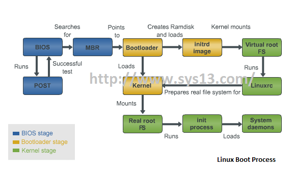
Linux boot process includes 3 stages:
1. The BIOS Stage
2. The bootloader Stage
3. The Kernel Stage


The BIOS Stage
The Linux boot process starts with the BIOS stage. The basic input/output system, BIOS is a small memory module on the motherboard. It's used during the boot process to initialize a system's hardware components.
The BIOS uses the information stored in the C MOS chip - another memory module on the motherboard that contains information about the system's hardware configuration.

During the boot process, the BIOS tests that all the hardware components on the motherboard are working. This is known as the power-on self-test (POST).


After performing the POST, the BIOS locates the drive or disk from which the OS must be booted. Typically it is configured to attempt to boot from a sequence of different devices in a certain order - so if the first listed device isn't available or doesn't work, the next one can be used. For a drive to be bootable, it must have a Master Boot Record (MBR) in it's first sector which is known as the boot sector. You need to format a disk to add an MBR to it's boot sector. You can also configure a system's hard disk as the primary boot disk and an optical drive as a secondary boot disk. This ensures that you can boot the OS from a removable disk if the main hard disk fails and the computer won't boot normally.

Bootloader Stage
After the BIOS stage, the bootloader stage involves loading two types of pre-cursor software into memory. The first pre-cursor software that's loaded during the bootloader stage provides enough information for the OS to be loaded into memory. The bootloader is usually found in the MBR of the boot disk. After the bootloader is loaded, the CPU can access the disk and memory(RAM). The other pre-cursor software that's loaded during the bootloader stage is an image of a temporary virtual file system called the initrd image or initial RAMdisk. This prepares the system so that the actual root file system can be mounted. It performs steps such as detecting the device that contains the file system and loading required modules. At the end of the bootloader stage, the bootloader loads the kernel into memory.

The Kernel Stage
In the kernel stage, the virtual root file system created by the initrd image runs the Linuxrc program. This program prepares the real file system for the kernel and then dismounts the initrd image.

The Kernel checks for new hardware and loads any required device drivers. If then mounts the actual root file system. Finally, it runs the init process.

The init process uses the parameters in the /etc/inittab file to load the rest of the system daemons. Once this process finishes, you can log in and use the system.

The most common bootloaders for Linux are LILO(Linux Loader) and GRUB (Grand Unified Bootloader). Both these bootloaders enable you to choose which OS kernel to load during boot time.

Storage Devices


Floppy Disks
Solid State Drives or SSDs
Optical Storage Devices
Flash Drives
Hard Disk Drives

Floppy Disks

A floppy disk consists of a thin, oxide-coated magnetic disk that's protected within a hard, plastic shell. They are largely obsolete. They can store a maximum of 1.44 MB per 3.5" disk and have slow data transfer rates.

They are also vulnerable to damage due to environment conditions such as heat and condensation.


SSDs

It uses integrated circuits to store data. It can be used in place of a hard drive. Like a hard drive it uses SATA(Serial Advanced Technology Attachment) interface and block I/O operations

An advantage of SSD over a hard drive is that it doesn't contain any moving parts. This reduces noise and the potential for damage through wear and tear.

It uses non-volatile memory chips that don't lose data when a system's power is off. This technology makes the SSD faster and more energy efficient but more expensive than hard disk.

Optical Storage Devices

CDs, DVDs are examples of Optical Storage Devices.

CDs and DVDs store data in lands and pits. The lands represent 1 and the pits represent 0 in binary computing. The coputer transforms the binary or digital data into user friendly format.

CDs are 1220 mm in diameter and are 1.2 mm thick. They can store up to 700 MB of data/74 minutes of audio content.
Single sided DVD can store up to 4.7 GB of data/120 minutes of audio content. Dual later can store approximately twice the amount of data as single sided DVDs.

Flash Drives

Small, portable, external storage devices that can store a large amount of data. It uses a flash memory chip which does not depend on electric current to retain data.

Hard Disk Drive

A hard disk drive is a computer's main storage device. It consists of multiple platters coated with a magnetic surface material. The drive reads information from these platters and writes information to them.

The speed at which theplatters spin determines how fast the disk reads and writes information. Modern disk speeds range from 4,200 RPM for low power portable drives to 15,000 RPM for high end server-based drives.

3 Types of Hard drives

IDE (Integrated Drive Electronics)
SATA (Serial Advanced Technology Attachment)
SCSI (Small Computer System Interface)


IDE (Integrated Drive Electronics)

A 40-pin, 80-wire ribbon cable connects an IDE drive and other devices to the IDE interface on a computer's motherboard.

Most motherboards with an integrated IDE controller include 2 IDE channels: Primary and Secondary. You can install a master drive and a slave drive on each. Slave drive provide extra storage space or serve as a backup drive.

By default, the master drive on the primary channel is used as the boot drive however you can change this using the CMOS setup program.

You cannot have more than 1 master or slave drives on the same channel.


SATA (Serial Advanced Technology Attachment)

They use a point-to-point connection topology, so that each SATA drive has it's own hard disk channel and bandwidth isn't shared between different devices or controllers. This makes SATA drives faster than IDE drives.

SATA bus uses 2 channels, one for transmitting dataserially bit by bit and another for conforming the reciept of data to the sender.


SCSI (Small Computer System Interface)


External SCSI hard drives connect in a communication chain. Rather than connecting each drive directly to the controller, only the first device connects to the controller and the subsequent SCSI devices connects to the one before it. Using many parallel drives is a benefit of SCSI as it provides constant and reliable access.

The controller has 2 connectors. An internal connector that connects all devices inside a server with a ribbon cable and an external connector connects all external devices to the controller.

Each device in the chain has a unique ID. The SCSI controller uses this ID to send data to the appropriate device. Early controllers supports upto 7 devices plus the controller with IDs 0 to 7. Modern ones supports upto 15 devices plus the controller with IDs 0 to 15. The higher a device's SCSI ID, the higher it's priority.

Installation Error 1935: An error occurred during the installation of assembly.

Error 1935. An error occurred during the installation of assembly

'Microsoft.VC80.MFCLOC,
version="8.0.50727.762",pubicKeyToken="1fc8b3b9a1e18e3b",processorArchitecture="amd64",type="win32"


This is issue occurs when you are trying to install Microsoft Visual C++ Redistributable package or when you are trying to install a software that needs Microsoft Visual C++ binaries.

This is typically the result of missing or corrupt files in the operating system. During the "Registering Product Information" section of the install process the installer "finalizes" the installation of the Microsoft runtime libraries. This finalization may include updates to the Windows Side-by-Side library configuration. In this case the installer is failing while updating the Windows Side-by-Side library configuration.


One of the following solutions must resolve this issue :-

1. Disable the Anti-virus.

2. Open an elavated command prompt and run the following comand:-

fsutil resource setautoreset true C:\

Reboot the system.

The "fsutil" command above will direct the "Transactional Resource Manager" to clean its metadata on the next drive mount.

3. Download and install the latest Msi installer from Microsoft

http://www.microsoft.com/downloads/details.aspx?displaylang=en&FamilyID=5a58b56f-60b6-4412-95b9-54d056d6f9f4

4. This issue may occurs due to the corrupt data store for .netframework. The .NET Framework cleanup tool is available for download at the following locations:

http://cid-27e6a35d1a492af7.skydrive.live.com/self.aspx/Blog_Tools/dotnetfx_cleanup_tool.zip
http://blogs.msdn.com/cfs-file.ashx/__key/CommunityServer-Components-PostAttachments/00-08-90-44-93/dotnetfx_5F00_cleanup_5F00_tool.zip

Save the cleanup log which will tell you what versions of .NET it cleaned and re-install them.

5. Enable the "Windows Modules Installer" service. Ensure that the Windows Installer service is set to "Manual"

6. This error has been observed when the insufficient permissions exist on this folder:

C:\Windows\winsxs\InstallTemp

The minimum needed (and default) permissions are:
Read & execute
List folder contents
Read
Write
Special permissions

7. If you do not find C:\Windows\winsxs\InstallTemp, then create an empty folder in C:\Windows\winsxs\ and name it as "InstallTemp".

8. If none of these works Run chkdsk.

Backup Exec Remote Agent Installation Fails for X and Y issues - A Workaround

Following is a workaround to install Backup Exec Remote Agent on a Windows machine. This is not a fix. There may be times when you cannot install RAWS due to Microsoft issues. For example, when windows installer is corrupted, error 1935, some .NET issues and times when you are left out with no troubleshooting.

TAKE A BACK OF REGISTRY BEFORE PERFORMING ANY REGISTRY CHANGES

You are unable to install the Backup Exec remote agent on SERVER - A for x reasons..

On Server - A

1. Uninstall the existing RAWS if present, Follow the above troubleshooting steps if the uninstallation fails.
2. Confirm to delete C:\Program Files\Symantec\Backup Exec folder.
3. Confirm you delete the following registry entries :
HKEY_LOCAL_MACHINE\SOFTWARE\Symantec\Backup Exec for Windows
HKEY_LOCAL_MACHINE\SYSTEM\CurrentControlSet\Services\BackupExecAgentAccelerator
HKEY_LOCAL_MACHINE\SYSTEM\CurrentControlSet\Services\PDVFSDriver
HKEY_LOCAL_MACHINE\SYSTEM\CurrentControlSet\Services\PDVFSNP
HKEY_LOCAL_MACHINE\SYSTEM\CurrentControlSet\Services\PDVFSService
4. Reboot the server.


5. From another server Server - B which abides the following conditions :-

-Same operating system as the Server - A.
-Same type as Server - A. Both 32 bit or Both 64 bit.
-Must have the Backup Exec remote agent installed and has the latest updates installed.

Copy C:\Program Files\Symantec\Backup Exec folder from Server - B and paste under C:\Program Files\Symantec in Server- A
OR just copy the entire Symantec folder.

6. Export the following registries from Server - B :-

HKEY_LOCAL_MACHINE\SOFTWARE\Symantec\Backup Exec for Windows
HKEY_LOCAL_MACHINE\SYSTEM\CurrentControlSet\Services\BackupExecAgentAccelerator
HKEY_LOCAL_MACHINE\SYSTEM\CurrentControlSet\Services\PDVFSDriver
HKEY_LOCAL_MACHINE\SYSTEM\CurrentControlSet\Services\PDVFSNP
HKEY_LOCAL_MACHINE\SYSTEM\CurrentControlSet\Services\PDVFSService

7.Import them to Server - A:-

8. Reboot Server - A.
9. Once the server boots up you will see that the remote server has been installed.
10. Confirm beremote service and error recording service are on running status.
11. Establish trust relationship. Confirm that the remote agent is publishing the correct IP address or Name.
12. Try running a backup. And it must be successfull.


The above solution will work in any case of remote agent installation failure. Visual C++ runtime redistributable package is a must for beremote service and error recording service to start. Without this package remote agent will not work. Same applies .NET.


Spaces between posts

I have been searching and searching and found so many instructions on how to remove the spacing between the posts.

I tried editing the HTML changing different themes and nothing worked. And found this silly thing while browsing through all the options on the dashboard.

"Show ads on blog" and this was chosen to be a "YES". Changed this to "NO" and Alas !! there you go.. the spacings between the posts became normal.

Go to the blog Dashboard >> click Earnings

On the right hand side, "Show ads on blog" Choose "NO"

I hope someone will find this information usefull.

ARP and ICMP protocols explained


ARP: Address Resolution Protocol


In order for the ip communication to take place between 2 computers it is necessary that the MAC address should be known to each other. If device A with ip address "192.168.1.11" needs to communicate with device B with IP address "192.168.1.1" and transfer data, device A should know the MAC address of device B.

* Used to find unknown MAC address using a known IP address.
* Used to find IP conflicts in the network.
* It is generated in the network layer and covered by datalink layer.


ICMP: Internet Control Message Protocol

* ICMP is a protocol generated in the Network Layer.
* This is the protocol used when you a ping(Packet Internet Groper) an IP address.
* While we ping an ip address, it will check the routing table.
* It will send echo requests and reply and shows success message if it is reachable or an error messages if it is not reachable.

While pinging if you get a "Destination Host Unreachable" message it means that the routing table does not have the network for the ip address you pinged. In this case the ping packet will not go out of your network as there is no route to reach the destination.

If you get "Request Timed Out" it means that it does have a rout to reach the pinged ip address but it will not get a reply from the pinged ip address.


Below is an illustration to explain ARP.


Now that the source knows the destination MAC they both can communicate with each other. As part of the PING request, the source generates an ICMP packet and then the destination responds back making the PING successfull.
PING request (ICMP prototol)

PING response(ICMP protocol)

And you get


IP ADDRESS (Internet Protocol Address) & Subnet Mask

There are 2 versions of IP addresses. IP version 4 and Version 6.

Ip version 6 will be soon introduced in real times. I will discuss ip version 6 on a later chapter. As of now lets discuss the ip version 4 which is the addressing scheme in use now.

Ip stands for Internet protocol. Formed by IANA(Internet Assigned Numbers Authority and ICANN(Internet Corporation for Assigned Number and Names).

* IPV4 is a logical address of 32 bits.
* An ip address is a combination of Network id and Host id just like a telephone number is a combination of area code and telephone number.
* First part is always the network part.

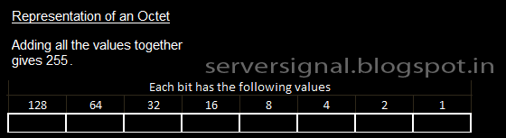
Each bit denotes a value of either 1 or 0. The 32 bit address is divided equally into 4 bytes.


IPv4 has 2 types.

1. Private which is used within a LAN. eg: at home
2. Public used in WAN. eg: Internet

PRIVATE IP address has 3 classes

Class A : 10.0.0.0 - 10.0.0.255

Class B : 172.16.0.0 - 172.31.255.255

Class C : 192.168.0.0 - 192.168.255.255

Apart from the above discussed ranges rest of the ip addresses are all public ip addresses.

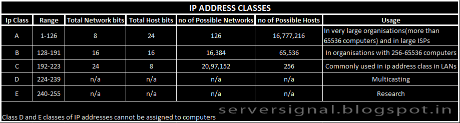
PUBLIC IP address has 5 classes

Class A : 1.0.0.0 - 126.255.255.255 (1-126 network)
(127 network is reserved for loop back)

Class B : 128.0.0.0 - 191.255.255.255 (128-191 network)

Class C : 192.0.0.0 - 223.255.255.255 (192-239 network)

Class D : 224.0.0.0 - 239.255.255.255 (224-239 network)

Class E : 240.0.0.0 - 255.255.255.255 (240-255 network)


SUBNET MASK

When you assign an ip address to a system, the system identifies the network part and host part of the ip address by looking at the subnet mask address.

All 1s on the network part and all 0s on the host part makes a subnet mask.

Look at the table.


DEFAULT GATEWAY

A default gateway can be termed as an access point to another network.

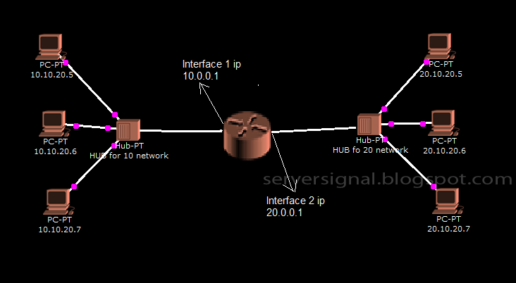
Suppose a computer in the 10 network needs to communicate with a computer in 20 network. Here comes the use a router. A router is used to connect 2 different networks. In the below picture you can see 2 networks. A connection is possible between these 2 networks using a router in between.


The interface where the 10 network is connected has an ip address 10.0.0.1 and the interface where 20 network is connected has an ip address 20.0.0.1.

10.0.0.1 is the gateway for computers in 10 network and
20.0.0.1 is the gateway for computers in the 20 network.


BROADCAST IP ADDRESS

As the term means, a broadcast ip address is used to sent a broadcast packet. In other words, if a packet or data needs to be sent to all computers in a specified network, broadcastip address is used.

By now you must be able to identify the network part and host part of an ip address. For an ip address 10.0.0.1, the first octet is the network part and the last 3 octets is the host part. Hence this ip belongs to the network 10.0.0.0. The broadcast ip for 10 network would be 10.255.255.255.

Similarly for an ip address 192.16.20.3, the network part is the first 3 octets and last octet is the host. Hence this ip belongs to the network 192.16.20.0. The broadcast ip for the network 192.16.20.0 is 192.16.20.255.

When you get all 1s on the host part and not changing anything on the network part you get the broadcast ip.

OSI Layers


OSI (Open System Interface)

It defines how data communication happens, the protocols involved.


PHYSICAL LAYER

* First layer of OSI model.
* Represents the bits.
* It deals with :-
Transmission media for data communication.
Electrical and mechanical functions of interface or ports or media.
Procedures and functions of transmission media.

Examples:
Hardware: Network adapter, Repeater, Network hub, Modem, Fiber Media Converter.
Protocols: DSL, ISDN all the physical topologies etc..


DATA LINK LAYER

* Second Layer
* Converts bits(0s and 1s) into Frames.
* Data link layer moves the frames from one hop to the other(from one network to the other).
* Physical addressing.
* Flow control.
* Error detection and error notification.
To detect errors, it uses a technology called CRC(Cyclic Redundancy Check).
* FCS (Frame Check Sequence)
* Access control >> The sender takes control of the reciever. Sender decides when to send the data.
* LLC and MAC work at this layer.

MAC Layer : It does the framing, physical addressing, line discipline, Error notification and error detection.

LLC Layer : Sequencing of bits and identifying the upper layer protocol.

Protocols : ARP, ARCnet, ATM, IEEE 802.2 (provides LLC functions to IEEE 802 MAC layers), IEEE 802.11 wireless LAN, Network Discovery, PPP, Frame Relay, Token Ring.


NETWORK LAYER

* Frames are converted to packets.
* Encapsulation of IP address takes place.
* Logical addressing.
Note: Addressing is done at the data link layer as well, but those addresses refer to local physical devices. In contrast, logical addresses are independent of particular hardware

and must be unique across an entire internetwork.
* Routing :- Determines the route through which the data has to be travelled.

Protocols: ipv4, v6, ICMP, IPsec, RIP, DDP.


TRANSPORT LAYER


* Packets are converted into segments.
* Sequencing : For each segment a sequence number is given. Each segment is put into correct sequence.
* Port addressing. Port service is chosen by Transport layer.
* Flow control: To avoid overloading, it controls the flow of data between 2 devices.
* Controls the flow of data.
* Error Control: Data is re-send from the source in case of error detection.

Protocols: TCP, UDP


SESSION LAYER

* Session is referred to as a network dialog. This is the layer which controls the network dialog between source and destination.
* Services like http, https, ftp etc are identified in this layer.
* It establishes, manages and terminates a session. This 3 step process is called dialog control.
* It creates synchronisation points/checkpoints which helps in continous flow of data in case a session is cut during communication.
* Mode of communication. ie 1.Duplex 2.Full Duplex 3. Semi-duplex.

Untill now the data is in the form of bits (os and 1s)


PRESENTATION LAYER

* Acts as a translator.
* Identifies the format of data.
* Encryption and Decryption is done in the layer.
* Compression and decompression.


APPLICATION LAYER

* It is the interface between user and application.
* E-mail comes in the application layer.
* File management, File transfer, file access, AD services are all in apllication layer.


Process of Encapsulation

If a data has to be transmitted it must be packaged by a process called encapsulation. As data moves down through each layer, each layer adds it's own header to the data before passing it to the next layer.

Below diagram will give you a better understanding.

Windows reboot loop "Configuring Updates: Stage 3 of 3"

This applies to Windows Vista, Windows 7 and Windows 2008 servers.

This usually happens after a windows update as was for me but also occurs when you update some drivers. Some commands which requires a reboot.

Your OS might scare you when you reboot and it says:  "Configuring Updates: Stage 3 of 3"

Dont worry try the following :-

1. Get into advanced boot options by hitting on F8 key. Try "Last Known Good Configuration". I promise this will not resolve your issue, but still it's worth giving a try.

2. Now that doesn't work. Get the respective OS installation CD and insert it into the CD drive. Reboot the computer and again get into advanced boot options, and select "Repair your computer" choose "Command Prompt" in the recovery choices.

3. Enter the following command:-

del C:\Windows\winsxs\pending.xml

4. Exit and reboot.

Good luck !!!!

Ethernet Cabling


Straight-Through Cables
Out of the 8 pins that exist on both ends of an Ethernet cable, each pin connects to the same pin on the opposite side. Straight-through cables are primarily used for connecting unlike devices.
A straight-through cable is typically used in the following situations:
Use a straight-through cable when:
  • Connecting a router to a hub
  • Connecting a computer to a swtich
  • Connecting a LAN port to a switch, hub, or computer

Note that some devices such as routers will have advanced circuitry, which enables them to use both crossover and straight-through cables. In general, however, straight-through cables will not connect a computer and router because they are not “unlike devices.”

Crossover Cables
Crossover cables are very similar to straight-through cables, except that they have pairs of wires that crisscross. This allows for two devices to communicate at the same time. Unlike straight-through cables, we use crossover cables to connect like devices.
Use a crossover cable when:
  • Connecting a computer to a router
  • Connecting a computer to a computer
  • Connecting a router to a router
  • Connecting a switch to a switch
  • Connecting a hub to a hub

Rollover Cables
Rollover cables essentially have one end of the cable wired exactly opposite from the other. This essentially "rolls over" the wires usually connect a device to a router or switch' s console port. This allows a programmer to make a connection to the router or switch, and program it as needed. It used to connect a computer terminal to a router's console port. This cable is typically flat (and has a light blue color) to help distinguish it from other types of network cabling. It gets the name rollover because the prinouts on one end are reversed from the other, as if the wire had been rolled over and you were viewing it from the other side.
This rollover cable is more commonly known as the Yost cable or more appropriately the "Yost Serial Device Wiring Standard".

Networking Devices
Networking devices are classified into two:-
1. DCE :- Data Communication Equipment. Ex: Hub, Switch
2. DTE :- Data Termination Equipment. Ex: PC, Router